electrical 2
- Body’s Ohm 150,000 600,00 Ohm
- Electric cause severe burn @ 200mA
- Cannot let go @ 15 - 20mA
- Ventricular fibrillation @ 100-200mA
- 1-8mA mild shock, let go @ will
- 8-15mA painful shock, may let go
Review
Ohm’s Law
\[V = IR\]Kichhoff’s Current Law
Sum of current into a node = sum of current out of that node \(I = I1+ I2\)
Period: one cycle (0 - 360 degree)
RMS: root mean square
Vrms = 120 V Vmax = Vrms / 0.707 Vint = Vmax * sineA
Period = 1 / f f frequency (Hz)
Vac + Vdc signals
When an AC sine wave and a DC source are placed together, the DC source is used as the AC sine wave reference center line.
\(V_{AVE} = Voltage (average) = V_{DC}\) \(V_{RRMS} = Voltage Ripple Root mean square = V_{AC}\) \(V^2_{RMS} = V^2_{DC} + V^2_{AC}\)
Circuit elements
Pushbuttons and switches
Pushbutton:
- One of the most used symbols in control schematics
- Contains both movable and stationary contacts
- NO - normally open
- NC - normally closed
- Double acting pushbutton: contains both normally open (NO) and normally closed (NC) contacts. – dash line represents a mechanical connection
Push-pull buttons:
- Are used to provide the start and stop functions in one push button (ex: emergency stop)
- Eliminates need for space for a second push button
Lighted push buttons:
- Used to indicate a specific status or operation of equipment
- Generally used to indicate motor running, stopped or tripped on overload
Switches (symbols):
NO - normally open switch NC - normally closed switch
Coil
- Represents coil of a relay, contactor or motor starter
Contacts
- NO - normally open
- NC - normally closed
Overload Relays
Overloads are designed to protect the motor from overload conditions Typically overload relays are designed to open the circuit when the current becomes 115% to 125% of the motor full load current. They must have some means of sensing motor current They must have some type of time delay (motors typically draw about 300% to 800% of full load current when started) Divided into two sections; the current sensing section and the contact section. OLHTR = overload heater
Manual Starter
The operator must go to the location of the starter to initiate any change of action
Single-Pole manual starter
Double-pol manual starter
As the overload heater (OLHTR) passes current, they heat up; if too much current passes through (which is an overload condition); the OLHTR causes a mechanical mechanism to trip and open the switch contacts disconnecting the motor from the power line.
Automatic Starter
A sensing pilot device is used with a manual starter to allow for automatic operation. (newer are electronic)
Relay
Are electro mechanical switches that contain auxiliary contacts Typically relays are used for small control applications (ex, 12V, 24V, 120V equipment) Contains contacts and a coil Used in single phase applications commonly
Contactor
Are similar to a replay but used for higher voltage and current applications ( ex: voltages 240V and above) Mainly used in 3 phase applications
2 types of control systems
2 wires: (or low voltage release)
Consists of typically on pilot device and output device connected directly Maintains original state before any action is applied to the pilot device (ex: sump pump, lights in a house) Low voltage release: the electrical devices continue to operate in their original state if power is lost. Examples:: sump pump, lights
3 wires: (or low voltage protection)
Consists of more than one pilot device connecting to one or more output devices MC symbols : they have directly relations (seal-in or hold-in contact & motor) Low voltage protection: the electrical devices revert back to the original state of the circuit, but the output is de-energized upon a power failure. (Example applications: conveyors, starter circuit for an engine
Timing Relays
Two general classifications: on-delay relay & off-relay On delay Relay (DOE - delay on energize); Applications: fan in a car on a cold day; lights; motors applications Off delay Relay (DODE - delay on de-energize); Applications: Cooling fan, radio, oven in house, garage door light, computer monitor; car light after power off and close door.
Pressure Switches
Used in systems where sensing pressure of pneumatic or hydraulic systems
Float switches
Typically used when a pump motor must be started and stopped when water (or liquid) level change.
Flow switches
Used to detect the movement of air or liquid through a duct or pipe
Limit switches
Used to detect when an object is present or absent from a particular location Can be activated by motion of a machine or the presence or absence of a particular object
Temperature (sensing) switches
Temperature measurements are done through sensing devices Sensing devices is not like a simple switch as it involves expansion and contraction of two different materials
Conductors
Have 1 to 3 valence electrons in their outer shell Can transmit electricity easily
Insulators
Have 5 or more in the outer shell Not readily transmit electricity
Semiconductors
Has 4 valence electrons in the valence shell Germanium (Ge) & silicon (Si) are used to create semiconductors
Doping
Take a pure (intrinsic) material and mix with an impure material in small quantities
P-N junction
Typically the voltage drop across the junction will be 0.7V
Diode
Made up of P-N junction, and allows current to flow in one direction current that flows through the diode when the diode is conducting is known as biased.
Depletion Region
Also known as the barrier between P-N materials.
Barrier Potential
Is the voltage required to allow current flow through the barrier. This is roughly around 0.65 → 0.7 V
PIV - (Peak Inverse Voltage)
-
This is the maximum reverse voltage that can be applied to a diode before it breaks down.
-
Diode reverse voltage is PIV
-
average forward current:
Diode
P-side - Anode (A) N-side - Cathode (K)j
Topics in First exam:
- Resistors, capacitors, and inductors: basic questions series, parallel
- Voltage, current, impedance
- Power (P - W), Reactive Power (Q - VARS), Apparent Power (S - VA)
- Safety basic questions
- Control schematics: 2-wire (low voltage release), 3-wire system (have low voltage protection ), basic questions
- Analysis a control circuit: give steps
- Identify control devices
- Capacitor pass current in AC&DC
- Relays, contactors
- Timing relay, float, pressure, temperature, limit, flow switches.
Retifier
Rectifier is a device or circuit that changes AC to DC
- Diode forward current
Half wave rectifier
- It is the simplest rectifier
- Consist of an AC source, diode and load connected in series
- easier to create, cheap
Diagram here:
\[I_{F} = I_{FORWARD} = I_{DIODE}\\ I_{Diode} = I_{Load}\\ V_{peak} = {\sqrt{2}} * {V_{source}}\\ V_{DC} = V_{peak} * {1 \over \pi}\\ PIV = V_{peak}\\ f_{load} = f_{supply}\\ I_{DC} = {1 \over \pi} * I_{peak}\\\]Ripple factor is how much AC is left after the conversion to DC; thus efficiency of conversion to DC.
$rf = 121\%$
Example:
To find ripple factor use this equation
\[rf = {VAC(load) \over VDC(load} * 100 \%\]- Step 1: Find VDC(load)
\(VDC(load) = Vpeak * 1 / pi = 120V/0.707 x 1/pi = 54V\) \(VAC(load) = Vsource x square(2) = 120V\) \(VAC(load) = 169V\) \(rf = 169V/54V x 100 = 121\)
Full wave (single phase) rectifier
- two specific types of full wave: center tap 1 & full wave
Center tapped full wave rectifier
- very popular, used for low voltage dc output where transformer is required
- very inexpensive to setup
- consists of half wave rectifier duplicated
- examples: battery chargers for recreational vehicle.
Diagram here
\[I_{load} = 2*I_{diode}\\ V_{peak} = {\sqrt{2}} * {V_{source(sec)}}\\ V_{DC} = {2 \over \pi }*V_{peak} = 0.637 * {V_{peak}}\\ PIV = V_{peak} (entire\ secondary) = 2 V_{source}\\ f_{load} = 2 * f_{supply}\\ rf = 48\%\\\]Full wave bridge rectifier
- provides rectification like center-tap but it utilizes 4 diodes
- manufactures make them with all 4 diodes in one package
- use for high voltage applications, reliable
- expensive
Diagram
Problems short -> short the supply open -> half way rectifier
Three Phase Half Way Rectifier
- majority of industrial applications need large amounts of dc power
- used for driving a dc motor, or as input to a VFDs (variable frequency drive)
Diagram
Wave form
\[V_{line} = V_{AB} = V_{BC} = V_{CA}\\ V_{phase} = V_{AN} = V_{BN} = V_{CN}\\ V_{line} = \sqrt{3} * V_{phase}\\ 3I_{diode} = I_{load}\\ V_{peak} = {\sqrt{2}} * V_{phase} \\ V_{DC} = 0.827*V_{peak} \\ PIV = V_{peak}(line\ voltage) = \sqrt{3} * V_{peak}\\ f_{load} = 3 * f_{supply}\\ rf = 17.7\%\\\]Three phase full wave bridge rectifier
- very common in industry for high voltage & current application
Diagram
\[I_{load} = 3*I_{Diode}\\ V_{peak} = \sqrt{2}*V_{line}\\ V_{DC} = {3 \over \pi} * V_{peak} = 0.955*V_{peak}\\ PIV = V_{peak}\\ f_{load} = 6*f_{supply}\\ rf = 4.5\%\\\]RC - resistor capacitor circuit
- Add capacitor to improve rf, close to zero; thus improving dc power output
- Capacitor is almost like a short
- Charge in positive cycle
- Discharge in negative cycle; thus improving dc
T (period for charging) = RC
LAB 6 Theory Measurement
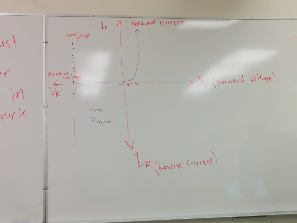
\[Vave = 0 V\\ Vrms = 120V\\ Vbd = Vave = 2/pi Vpeak\\ Vab = Vave (don't care)\\\]Zener Diode
- special device designed to operate in reverse polarity
- when this diode operates in this reverse direction, it is known as the Zener region.
- usually if a diode operates at a high voltage in the Zener region, it would be destroyed; but the zener diode is designed to operate in this region.
- the supply voltage must be greater than the voltage of the Zener diode in order for it to work.
- maintain 12V voltage
Graph:
symbol:
Example:
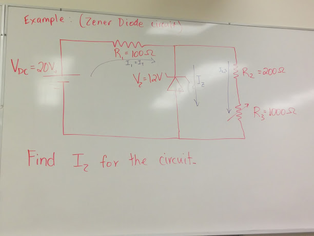
Find I_2 for the circuit
- Step 1: find the resistance for R2 and R3 \(R_{2,3} = R_2 + R_3 = 20 + 1000 = 1.2k\Omega\)
- Step 2: Find \(I_{2,3} = {V_{2,3} \over R_{2,3}} = {V_{z} \over R_{2,3}} = {12V \over 1.2k\Omega} = 0.01A = 10m\)
- Step 3: If there is 12 V_dc for the paprallel branches, that means that R_1 sees \((20V - 12V) = 8V = V_1\) \(I_1 = I_T = {V_1/R_1} = {8V / 100\Omega} = 80mA\)
- Step 4: To find current though the zener diode, we subtract I_{2,3} from I_1 \(I_1 = I_2 + I_{2,3}\) \(I_2 = I_1 - I_{2,3}\) \(I_z = 80mA - 10mA = 70mA\)
Transistors (BJT: Bipolar Junction Transistor)
- made by connecting 3 pieces of semiconductor material
- there are two basic types of transistors: NPN and PNP
- it is an electric valve that allow current flow through the collector and emitter, when where is a current flow through the base & emitter
- a small current flow of say 1mA through the base and emitter, can have the collector & emitter flow around 100mA
- with an increase or decrease in base & emitter current, the collector & emitter current also increase and decrease
- transistor saturation region: there’s full collector current flow through transistor
- transistor cutoff region: there’s no collector current flow through transistor
- Applications
- switches
- amplifiers
- 3 elements: base, collector, and emitter; base->emitter is the trigger for flow in collector & emitter.
- NPN: Base(+); PNP: Base(-)
- the emitter is only on the other side of arrow
- current flow from P to N
- need to switch batteries polarity when changing NPN to PNP
Physical layout:
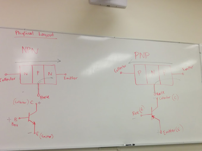
-
NPN (more common)
-
PNP
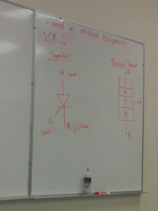
SCR (Silicon Controlled Rectifier)
- thyristors, specifically SCRs are the most used and oldest semiconductor power control devices in industry today
- used in primary power control in all DC motors, and in large AC motors drives
- used in mining equipment
- is a three terminal, 4 layers semiconductor device primarily used as a switching element or device
- SCR is a rectifier, only allows current flow in one direction like a diode
- basic difference is that it will not conduct current or forward bias until its gate receives a positive pulse of current
- Commutation: turning an SCR OFF after it has been conducting current, 3 ways to commutate SCR
- Natural commutation: push NO button, creating a short across the SCR, then the SCR is OFF because of the short
- Class F commutation: the SCR is turned OFF automatically by AC source, it need to be turned on after each AC cycle
- Forced commutation: by using capacitor connected in para with the SCR
- Summary:
- the SCR is OFF, until an initial gate current pulse
- the SCR is ON with a gate pulse
- once its ON, the SCR remains on until the current flow through the anode and cathode is so low that it drops out of conduction
Symbol
EXAM: everything up to this point**
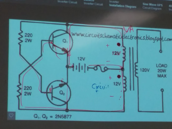
inverter
- convert DV voltage into ac voltage
transformer
-
have a primary and secondary side with typically a steel core.
-
laminations are used to reduce eddy current losses between each of the core sheet elements
-
the high side of transformer (more windings) is denoted as H
-
the low side of transformer (less windings) is denoted as X
-
there are 3 functions for a transformer
-
H side: high number of windings; X side: low number of windings
-
primary side’s connected to the source; secondary side’s connected to the load.
-
High side has higher resistance; low side has lower resistance.
-
step down: the voltage is decreased as the H has the source voltage and the X side is connected to the load
-
step up: the voltage increase as the X side is connected to the source and the H side is connected to the load
-
isolation: the voltage of both the H & X sides is the same, but the two side are electrically isolated from each other (for protection purpose, don’t create damage on the other side )
-
Transformers are rated in VA (Volt-Amps)
-
N is number of windings; a is turns ratio
-
dc machines
- general:
- in the past generating large dc currents required dc generators
- but with the advent of solid-state commutators, such as diode, SCR banks, dc generators have rudundant.
- vast majority of power is generated by alternators and then converted with solid state electronic devices.
- dc motor are prevalent and will be so for some time
- dc motors speed may easily be adjusted in very fine increments from standstill to rated speed and above
- it not properly regulated; speeds can go high enough to cause destruction by centrifugal force
- developed rated torque at all speeds
- the torque created at standstill is many times greater than torque developed by AC motor of equal power and speed ratings.
- but some (AC) induction motors can now perform tasks that at one time only be done by a dc motor.
- how components work
- principal is a stationary field and a rotating armature.
- permanent magnet field machine popular
- field flux is established by electromagnets (in series or parallel fields)
- parallel fields
- referred as a shunt field, connected in parallel with the armature
- most machines, the shunt is not typically connected dirrectly in parralel with the armature (seelf-excited), denoted F1, F2, but connected to seperated source.
- series fields
- connected in series with the armature, denoted S1, S2
- motor: connection high to low (F2-2 to F1-1)
- generator: connection low to high (F2-1 to F1-2)
- the armature develops is own flux with using shunt and/or series field flux, producing torque when machine is setup as a motor
- the frame has 4 functions
- provides rigid support of the field magnets
- provides a good magnetic path
- support the end bells and bearing housing
- disipate heat
- armature core and commutator are assembled on the shaft
- commutator ensures that the armature current is reversed when the armature is rotating; this also ensures the torque is in the same direction
dc generator
- very rarely used; except for specialized applications as engine-driven welders
- many still in service are in elevators, surface mining equipment, exciters, welders and drilling equipment.
- the standard direction of rotation facing the commutator end (end opposite to the drive end) is clockwise
- direction of current flow is through the windings from lower to higher numeral (A2 - positive terminal, A2 - negative terminal)
dc motor
- stator has constant magnetic field
- rotating armature connected to dc source
- even if new advances in the induction motor, it has not made the DC motor obsolete
- still found in hoists, mining trucks, locomotives, trolley buses, drilling rigs and automotive
- Advantages
- exellent starting torque
- simple soft starting
- exellent speed control
- good horse power
- unity power factor
- Disavantages
- becomming less popular due to high initial cost and high maintenance
- maintenance personnel must have knowledge of the DC motor characteristics to order replacement parts.
- the armature is engergized from a three phase source through a three phase bridge rectifier. (using 3 diodes, and 3 SCRs)
- DC motor efficiency
- n = P_out / P_in (motor efficiency n) is a ratio of output power to the input power.
- motors have 2 types of losses: fixed loss and variable losses (eddy, connections).
- fixed losses are around 3-6%
- variable losses are around 3-15%
shunt field motor
- popular in the past
- speed regulation is close to that of an induction motor (5%)
- starting torque is good 150% of full load torque
- considered as a constant speed motor
- applications:
- machine tools
- centrifugal pumps
- fans
- conveyors
series field motor
- most common in existence today
- poor speed regulation, but very high starting torque
- good power-to-size ratio
- other than a small motors, series are NEVER connected by pulleys or belts because of the instant high torque can cause belt slipt
- accidental disconnection from the load which will cause overspeeding.
- loads are connected usually to motor shafts using splines, gears, or pinions (safe)
- applications
- use in mining and hoisting, such as bucket, wheels, draglines, traction motor in off-road trucks, etc.
- portable drills, grinders, chain saws.
compound field motor
- can be operated safely at no load
- poor speed regulation compared to shunt motor (15-25%), but more torque
- machine could be started as series motors (for torque), and once at the rated speed, the series windings could be by passed, then operate as shunt (for speed regulation).
- disavantages: expensive machine
- only the armature current can be reversed, or both field could oppose each other (the shunt current can’t)
example 1
a dc generator provide electrical power of 1300 kw, the efficiency of the generator is 88%
a) what is the mechanical power delivered to the generator (hp) ?
\[n = {P_{elec} \over P_{mech}} * 100\%\\ P_{mech} = {P_{elec} \over n} * 100\% = {1300kw \over 88 } * 100 = 1477kw = 1477000w * 1hp / 746w = 1980hp\]- n = generator efficiency
- \(P_{mech}\) mechanical power
- \(P_{elec}\) electrical power
b) how much power is lost in the generator?
\[P_{in} = P_{out}\\ P_{mech} = P_{loss} + P_{elec}\\ P_{loss} = P_{mech} - P_{elec}\\ P_{loss} = 1477kw - 1300kw = 177kw = 237hp\\ P_{loss(\%)} = {P_{loss} \over P_{mech}} * 100\% = {177kw \over 1477kw} * 100\% = 12\%\]example 2
a dc motor supplies 2.5 hp of mechanical power to a load. If the efficiency is 78%, how much electrical power is drawn (kw)?
\[P_{mech} = 2.5hp * 746 w/hp = 1865w\\ n = {P_{mech} \over P_{elec}} * 100\%\\ P_{elec} = {1865 \over 78 } * 100 ~ 2400w\]inductor machines
induction motor
- commonly used electrical machines for vast majority applications
- used for commercial installations from small fractional horsepower motors to machines rated in megawatts
- with recent, more reliable frequency changing devices and new rotor designs induction machines can replace almost any application involving a DC machines
- cheaper, rugged, and easier too maintain than other alternatives
rotating magnetic field
- to best understand the induction motor, the stator has an electrical connection to the AC source
- the stator generates a flux with the changing AC current flow in the windings embedded in the stator
- this flux that is generated causes a rotating magnetic field (similar to transformer action)
speed, frequency, and poles
- supply frequency & number of poles determine the speed at which the stator magnetic field rotates
- low frequency means low speed
- 60 is used to measure revolutions per minute
- \(n_{s}\) is the stator synchronous speed (rated speed)
- the rotor will always be rotating slightly less than synchronous speed
- the difference between synchronous speed and rotor speed is called slip
- the current induced on the rotor from the rotating magnetic flux of the stator develops rotational motion or torque.
- since this occurs, it is known to be self-starting when AC voltage is applied to the stator windings
- any air gap within the induction motor is a detriment; certain minimum distances are maintained for practical reasons
- rotor will accelerate in the direction of the rotating flux in an attempt to catch up
- along with this, both voltage and reactance is reduced by the slip as the rotor tries to reach synchronous speed
- some features
- highest starting current
- poorest power factor; maximum power is developed when rotor power factor is 0.707
- highest rotor frequency at start
- two types of induction motor: wound rotor, squirrel cage
synchronous machines
synchronous alternators
- 4 major components: stator, rotor, exciter, and frame and shaft assembly
stator
- known as the stationary armature, including the armature windings and the armature iron
- armature iron is made of silicon steel that is laminated to reduce hystersis and eddy current losses
- armature windings are fitted into stator slots
- operating voltages range from typically 200 - 600V and can be custom designed for any high voltage (usually under 15kV)
- voltage is induced into the armature windings from the rotating magnetic field
- advantages of stationary armature design versus rotating armature design
- rotor can be lighter and smaller since it carries less current and lower voltage
- only two slip rings are required instead of three
- high current and voltage connections can be made easily
- deeper slots in the stator can handle large wires.
- slots diverge allow for lower reluctance which allow more current to flow.
- better heat dissipation and easier cooling methods
- heat is removed from the windings either by direct contact with gas within the machine enclosure or by contact with the stator
- winding and bearing temperature and vibration sensors may also be placed within the stator
rotor
- the rotating field or rotor of synchronous alternator produces the flux that allows operation of a generator
- the required flux is generated by passing a direct current through the winding
- on large rotors the field windings consist of copper bars rather than wire to handle large field current
- varying amounts of dc current is needed to produce the required flux to energize the windings
- for brushless machines, the current is generated right on the rotating shaft and fed into the field
- brush-type machines, the current is fed into the field via slip rings and brushes
- moving air or gas helps cool the stator, also cools the field (rotor)
- many machines have a rotor mounted cooling fan that pulls air across the windings
- rotors have a second winding mounted in the pole faces; that are called amortissear windings.
- amortisseur windings are used for damping torque pulses on the alternator shafts
- two designs for the rotor
- salient pole or definite pole rotor
- fitted into stators that are wound for four poles or more.
- intended for slow or medium speed operation so require many poles
- machine is used as an alternator, the prime movers will be hydro and/or diesel & gas engines for medium speed
- cylindrical pole rotor
- resembles a cylinder, also known as a round rotor or turbo rotor
- rotors are long and relatively small diameter fields
- usually only support two poles (but some are 4 poles)
- if more poles are needed than 4, would then use salient type construction
- the long, smooth rotors lend themselves to high speed, low vibration operation
- commonly found on turbine-driven alternators
- salient pole or definite pole rotor
exciter
-
exciter is a method of supplying dc current to the rotating field to produce magnetic flux
-
brushless excitation system uses an ac generator mounted on the same shaft of the rotor
- output from this generator is rectified by a rotating rectifier bridge; fed directly into rotor without slip rings.
frame and shaft assembly
- designed to complete the magnetic circuit of the field
- supports the stator windings and shaft assembly with its end bells on smaller machines
- shaft assembly is made up of the
- exciter (if mounted)
- slip rings (if used)
- field iron
- field windings
- fan
- bearing
- insulating material
- the amount of voltage generated in the armature of an alternator is dependent on
- no of armature turns per coil
- speed of the rotating field
- amount of flux produced by the field
- the amount of flux is dependent on three factors
- number of turns of field windings
- type of core material (or iron) the rotor is made of
- the amount of current flowing through the field windings
rotational losses
- brearing friction
- slip ring to brush friction
- friction of the rotor and fan (windage)
core losses
- iron losses
- core losses
- exictatioon losses
- magnetization losses
- (internally) eddy current and hysteris losses